Coordination between “ILS”, “PAPI”, “Aiming Point”
In this section, I would try to explain something about coordination between “ILS”, “PAPI”, “Aiming Point”.
Runway Category I, Category II, Category III, are all runways with an Instrumental Precision Approach. Therefore the three different systems: “ILS”, “PAPI” and the horizontal signs “Aiming Point” have to be coordinated together, in order to give the same information to the pilot.
All the three systems have to be in according with the same data:
- approach slope
- “MEHT” minimum eye height over the threshold
Approach slope
Usually the slope path has the value of 3°. Different angle of slope path can be adopted, according with the environmental condition, like obstacles on the landing final approach and so on.
“MEHT” minimum eye height over the threshold
About MEHT [minimum eye height over the threshold], we have to refer to the ICAO Annex 14, table 5-2.
 The MEHT [minimum eye height over the threshold] is the sum of MWC [Minimum wheel clearance] and EWH [Eye-to-wheel height] of airplane in landing configuration. See figure n.01
MEHT = MWC + EWH
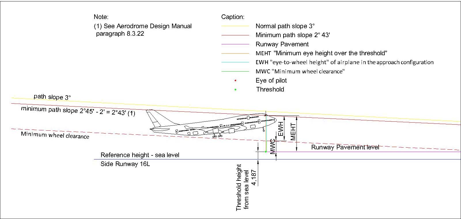 Figure n.01
In table 5-2 we can see 4 different groups of “Eye to wheel height”, which depend by the type of aircraft.
To decide which group choose, we have to refer to the ICAO Aerodrome Design Manual Part 4, Appendix 6).
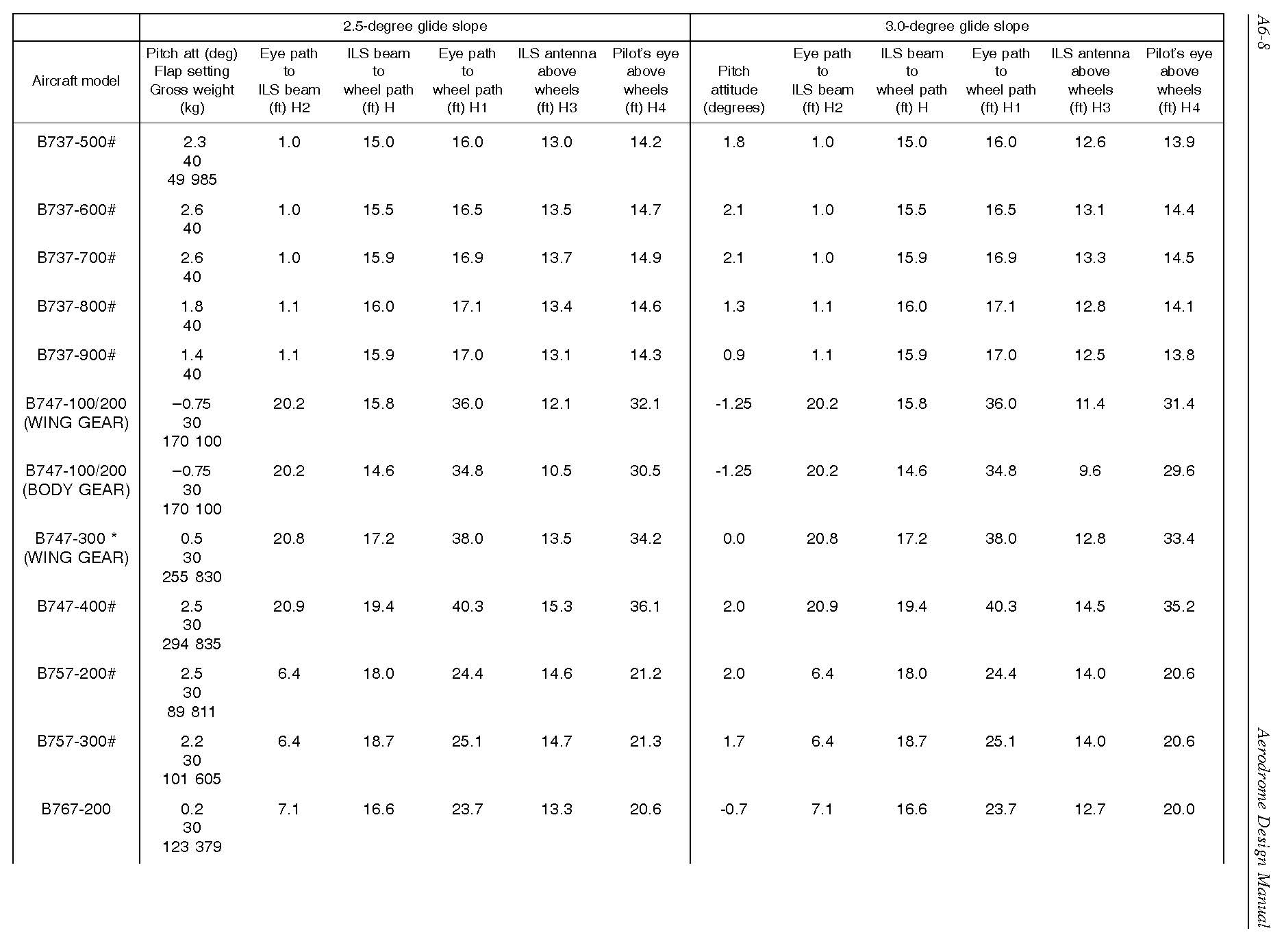
ICAO Aerodrome Design Manual Part 4, Appendix 6) – extract from pag 8
Let’s have an example.
Suppose we have to land on the runway with a Boeing 747-400. On the ICAO Aerodrome Design Manual Part 4, Appendix 6), we can determined 40,3ft (12,28m) for pilot’s eye above wheel with 3.0 degree of glide slope.
On the table 5-2, we have to choose the fourth group, EWH[eye-to-wheel height of airplane in the approach configuration] 8m up to but not included 14m. The MWC [Minimum wheel clearance] for this group is 6,00m.
About EWH[eye-to-wheel height of airplane in the approach configuration] we have to choose EWH = 14m in favor of safety. In that way all the aircraft with 8 < EWH > 14 are verified.
Therefore:
- EWH = 14,00m
- MWC = 6,00m.
The MEHT is: MEHT = MWC + EWH = 6,00 + 14,00 = 20,00m
With the data above reported we can calculate the installation distance of PAPI system, ILS system and “Aiming Point” signs.
On the internet we can find lots of literature for the mathematical calculation of the installation distance. The best, in my opinion, it is the Advisory Circular AC 302-009 issued by Canada Transport.
Therefore I want to show, how to determine the installation distance by drawing. We could use CAD software. The results will be very accurate, and we can also verify with our eyes what we are doing!
I’ll show an example from my calculation for the rehabilitation of RWY 16L/34R in Fiumicino Airport – Italy.
The runway data are:
- Runway Length 3.901,87m
- Threshold 16L Height from sea level 4,19m
- Threshold 34L Height from sea level 1,75m
We can use a CAD software to make a longitudinal section of the runway as shown in the figure n.02.
 Figure n.02
Suppose we have to land on the runway with a Boeing 747-400. We can use the same data determined at the beginning of this the article.
- EWH = 14,00m
- MWC = 6,00m
- MEHT = 20,00m
We can apply the above data to the figure n.02. In that way we obtain the figure n.03
 Figure n.03
Now we can draw a line crossing the “eye of pilot” point with a slope of 2° 43’. We name this line “minimum path slope”. Please do not take in consideration the path slope 3°, we’ll see after how to determine that.
Now we have to draw an horizontal line which represents the altitude of the “Conventional Optical Reference” of PAPI system from sea level.
The Conventional Optical Reference” altitude is the sum of the “ground altitude” and the “PAPI Optical Center” from the ground. For “PAPI Optical Center” we have to refer to the data sheet of the PAPI equipment. According to the “Aerodrome Design Manual – part 4 – paragraph 3.3.27 : “PAPI units should be the minimum practicable height above the ground and not normally above 0.9 m. All units of a wing bar should ideally lie in the same horizontal plane …”
The intersection between the “minimum path slope” and the “Conventional Optical Reference” represents the distance of installation of the PAPI system. We name this point “Do”. See figure n.04.
Now we can draw a line crossing the “Do” point with a slope of 3°. This line represents the Normal path slope 3°.
The intersection between the “Normal path slope 3°” and the “Runway pavement” represents the distance of the Aiming Point. See figure n.04.
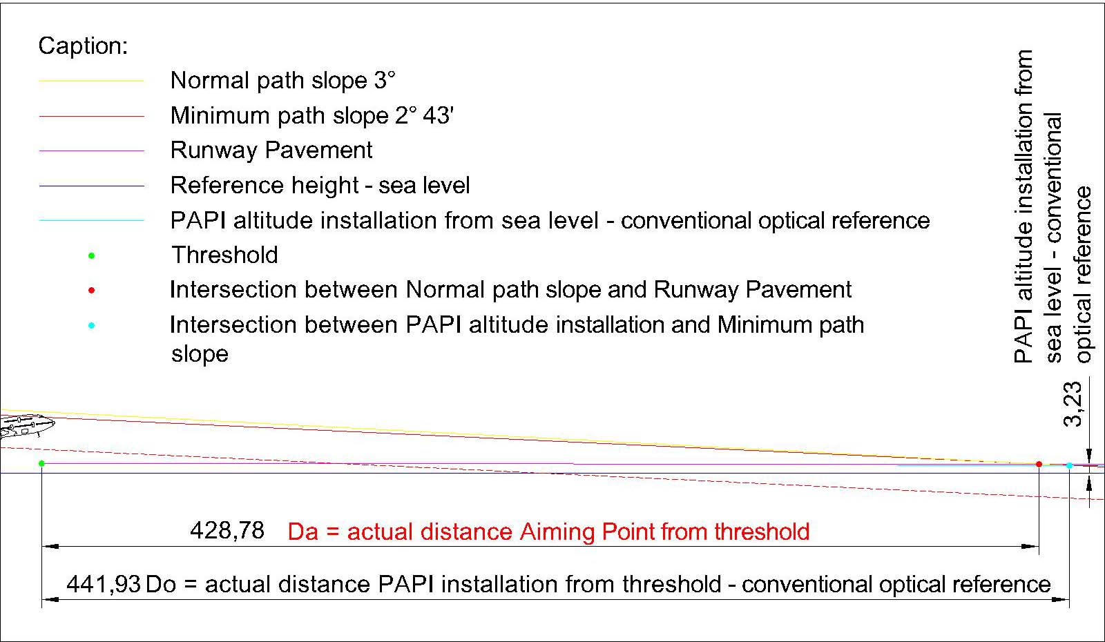 Figure n.04
To find the right position of the GP [Glide Path] antenna of the ILS System we have to determine the TCH [Threshold Crossing Height]. According to the FAA Order 6750.16E (Siting Criteria for Instrument Landing System) the TCH may vary from 40ft to 60ft. The typical value of TCH is 55ft (16,76m). See figure n. 05.
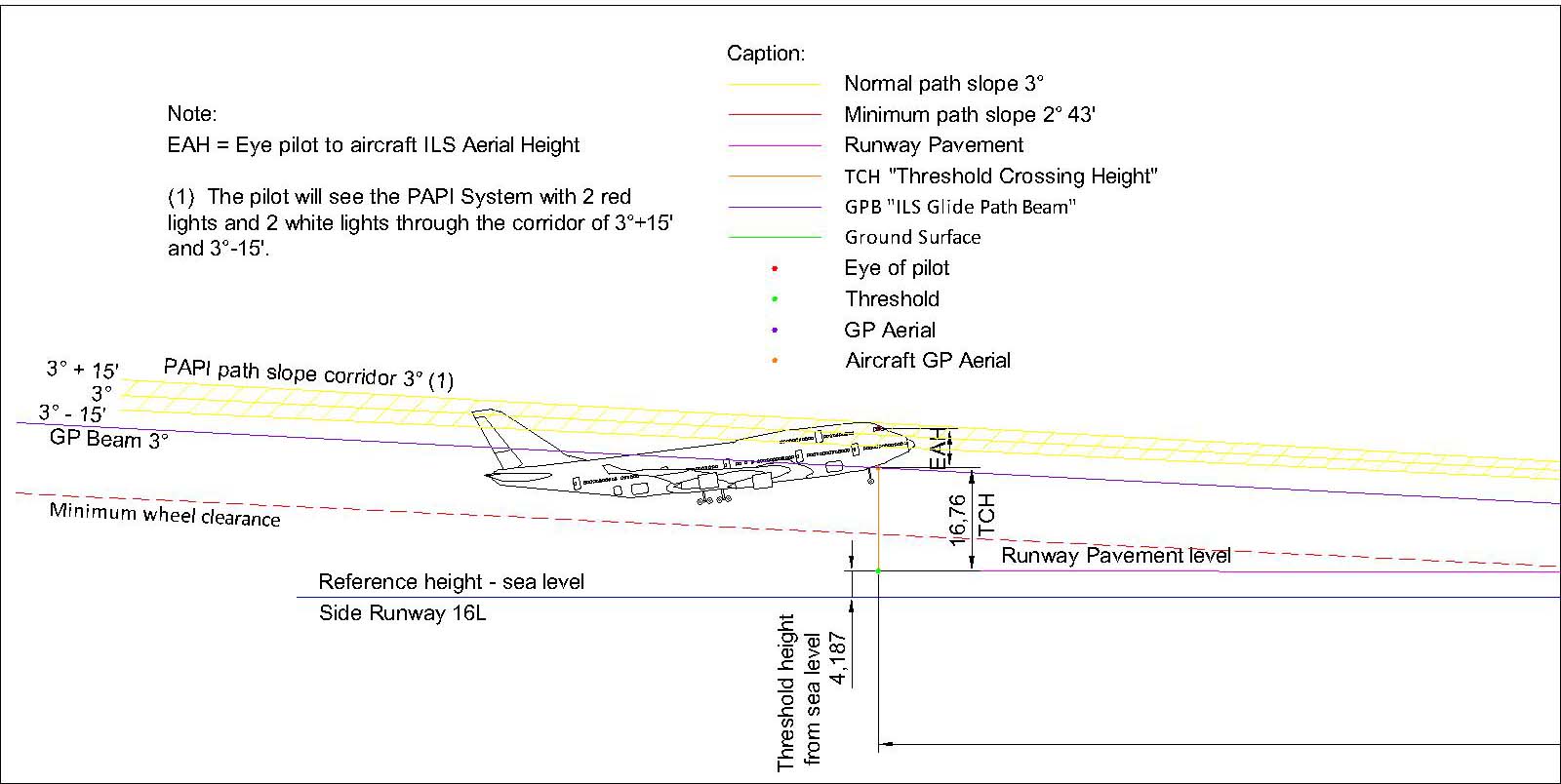 Figure n.05
We can draw a line crossing the TCH point, the name of this line is Glide Slope Beam 3°. To verify the coherence between the PAPI system and the ILS system we have to move the GP Aerial of the Aircraft onto the GP Beam line and verify if the eye of the pilot is still into the PAPI path corridor. We have to do that for each type of aircraft we want to use for the runway.
In order to find the right position of the GP antenna, we have to draw the ground surface around the predictable position. The intersection of the “Glide Slope Beam 3°” and the ground surface is the GP antenna position. See figure n. 06.
 Figure n.06