Aircraft Parking
In this section, I provide some basic informations to assist and support with the design of the aircraft parking. In particular I describe how to choose the best aircraft position on the stand, in relation to the ground services to be provided.
The ground services that are taken in consideration are the following:
- 400Hz ground power;
- Preconditioning air
- Hydrant fueling
According to the Federal Aviation Administration (FAA) guidelines, there are three different methodologies of aircraft parking:
- Co-located Cab
- Wing-aligned
- Common Stop Bar
The Co-located Cab method focus on the position of the front passenger door as a steady selection. Each different aircraft shall be parked on the stand, so that the front passenger door is positioned in the same location. This methodology is often used for the PBB “Pier Boarding Bridge”, and it leads to the following advantages:
- allows the PBB to operate with minimal movements, saving time for operators and increasing apron safety by restricting the swing movement of the PBB
- reduce the 400Hz cable length across the apron and minimize drop of voltage;
The Co-located Cab method causes to the following disadvantages:
- often necessitates multiple hydrant pit and air conditioning pit locations, especially in the following condition:
- when we want to park in the same stand different models of aircraft with different length of fuselage and different wing span, especially in case of different category of aircraft (wide body and narrow body);
- when dealing with a new layout;
The Co-located Cab method is depicted in Figure 1.
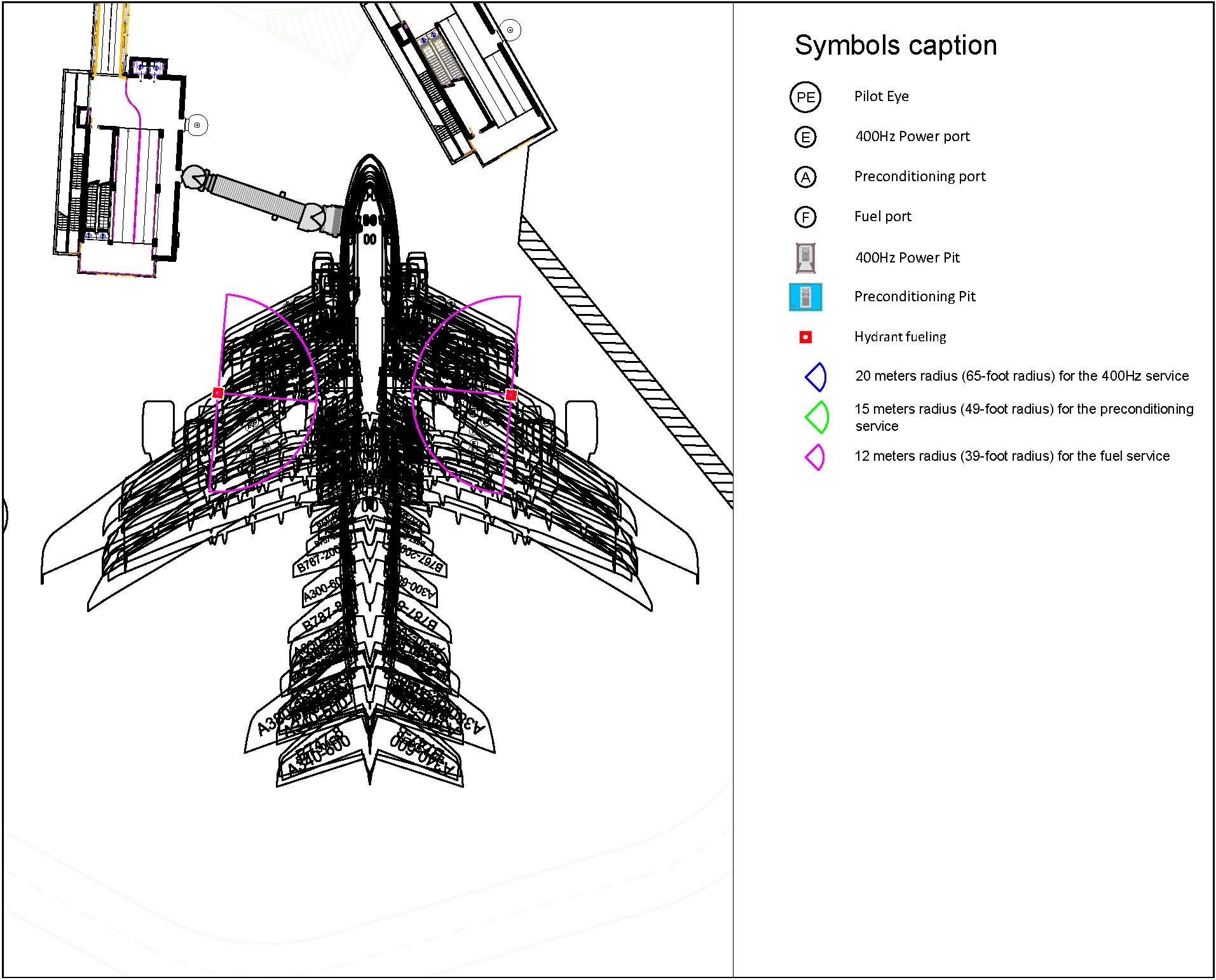 Figure 1 – Co-located Cab method
The wing-aligned method takes in consideration the hydrant fueling operation, the 400Hz pit service and the air conditioning service. Each different aircraft shall be parked on the stand, so that the front side of the wings is positioned in the same location. To achieve that is necessary to paint on the apron paving one specific stop bar for each specific aircraft model. The stop bar marking are located on the left side of the fuselage, and the pilot uses the marking to stop the aircraft when the stop bar strip, to be considered, is straight in line on his left side. The alignment of the aircraft main wings is such that all the above mentioned services are available:
- the fuel ports are within a 12 meters radius (39-foot radius) of the fuel-pit;
- the preconditioning ports are within a 15 meters radius (49-foot radius) of the preconditioning-pit;
- the 400Hz ground power ports are within a 20 meters radius (65-foot radius) of the 400Hz-pit.
The wing-aligned method leads to the following advantages
- reduces fuel hose length across the apron and minimizes actions for refueling personnel;
- increases safety for parking the cart at the same location and accessing the same fuel pit for each aircraft operation;
- reduces air-conditioning hose length across the apron and minimizes cold dispersion from the hose (the aircraft’s air conditioning connectors are usually located under the fuselage, where the main wing cross the fuselage);
The wing-aligned method causes the following disadvantage
- as the aircraft 400Hz power plug is located at the nose of the aircraft, in order to supply the short fuselage aircraft we need to extract all the 400Hz power cable from the pit. The 400Hz power cable will lay on the apron paving for all the time of the service.
- multiple stop bar markings, which could induce pilot to fail/miss the correct position.
The wing-aligned method is depicted in Figure 2.
 Figure 2 – Wing-aligned method
The common stop bar method focus on the position of the aircraft front side of the fuselage, as a steady selection. Each different aircraft is parked on the stand, so that the eyes of the pilot are straight in line with the designed stop bar marking, located at the pilot’s left side.
The common stop bar method leads to the following advantages
- provides the marshallers with minimal parking position options and reduces overall error;
- in self maneuvering stands without marshaller service, provides the pilots with minimal parking position options and reduces overall error;
- reduce the 400Hz cable length across the apron and minimize drop of voltage;
The common stop bar method causes to the following disadvantages
- difficulties to use the same hydrant fueling and air conditioning pit when parking on the stand different models of aircraft with different length of fuselage and different wing span;
- impossibility to use the same hydrant fueling and air conditioning pit when parking on the stand aircraft belonging to different categories: narrow-body (ICAO Category “C”) and wide-body (ICAO Category “E”);
The common stop bar method is depicted in Figure 3.
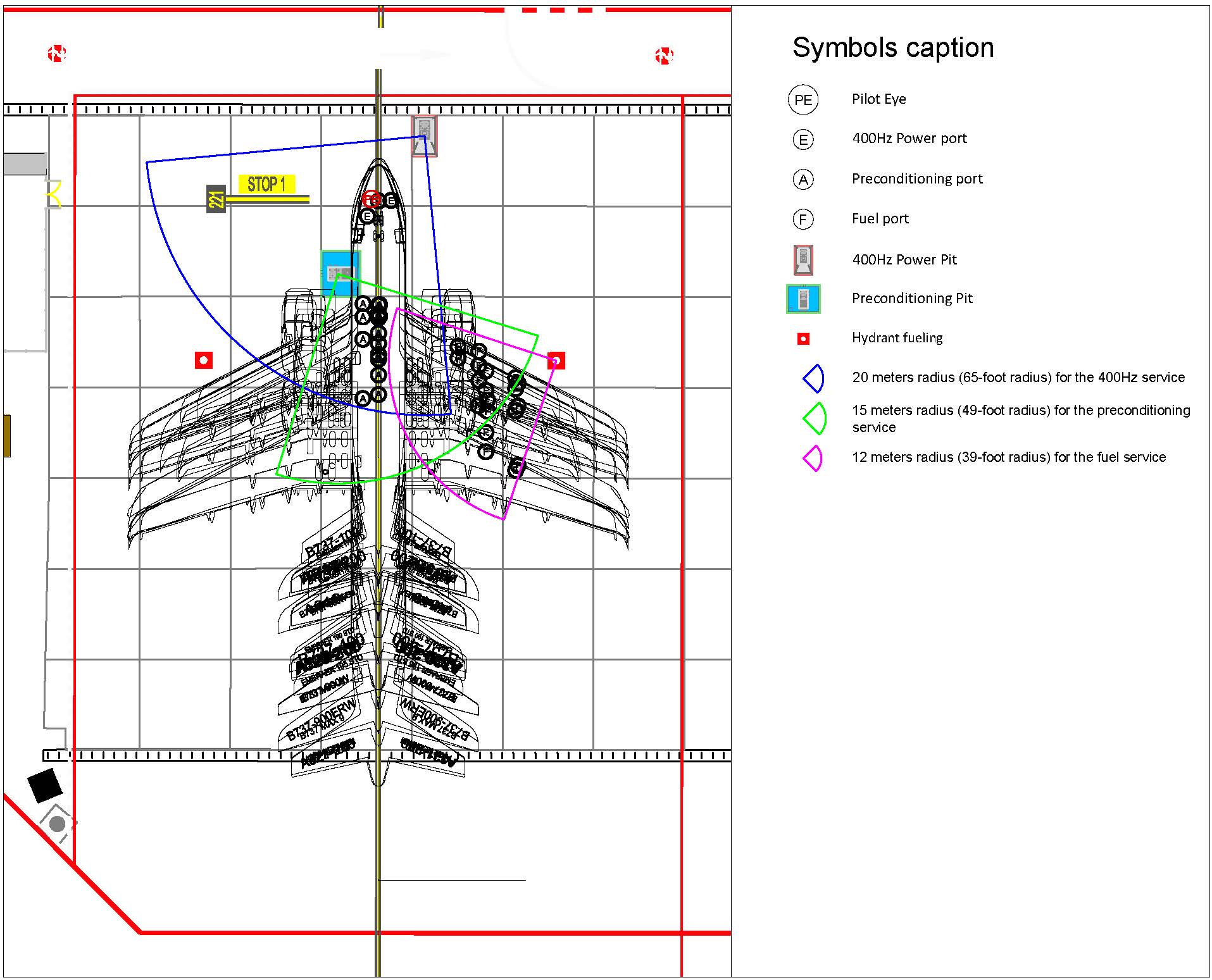 Figure 3 – Common stop bar method
Conclusion
The best solution in case of PBB “Pier Boarding Bridge” is the Co-located Cab method.
In case of “Remote Stands” my suggestion would be an optimization of the wing-aligned method in order to minimize the number of the stop bar markings. A study of the aircraft mix, intended to be parked on the stand, should be undertaken in order to collect similarly sized aircraft and assign them to a specific stop bar.
In the case of stands used only for aircraft ICAO category “C”, we can optimize and reduce the number of the Stop Bars to two different one. In the Figure n.4 is depicted one of the possible solutions.
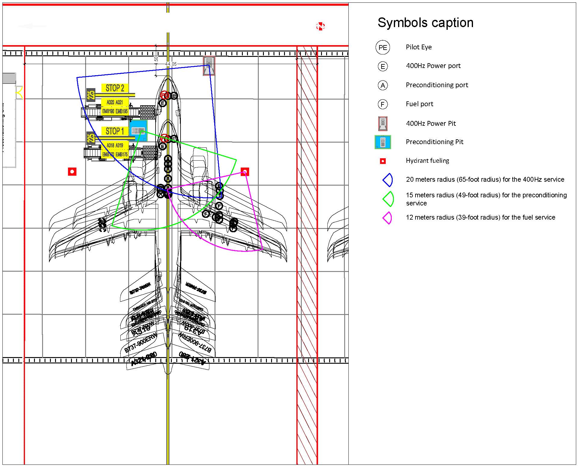 Figure 4 – Wing-aligned method with a minimum of number two stop bars.